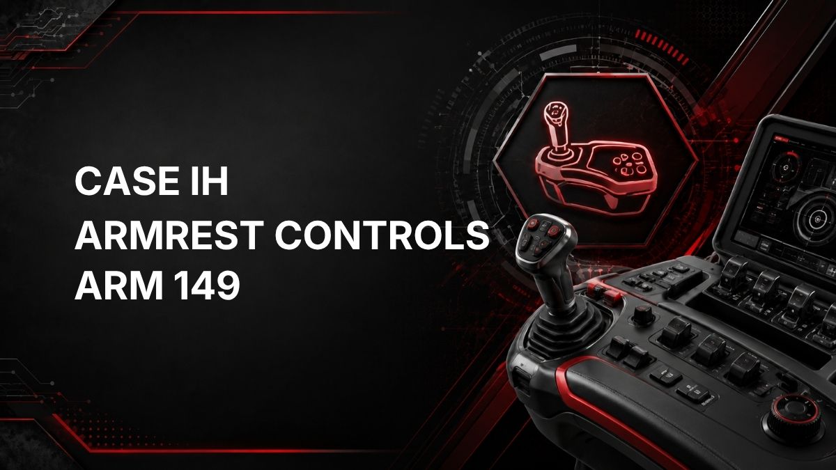
Case IH Tractor ARM 149 Fault Code: Hitch Upper Limit Potentiometer Failed
What Case IH ARM 149 Means
ARM 149 is a Case IH tractor fault code from the ARM controller, which relates to armrest controls. The official description is: Hitch UPPER LIMIT potentiometer is failed.
In practical terms, this fault indicates that the tractor has detected a problem with the potentiometer used for the hitch upper limit setting or feedback. The controller may not be receiving a valid or expected signal from that potentiometer. This guide is based on the official fault description only and does not assume a specific tractor model, component location, or measured test value.
Likely Symptoms
Symptoms can vary depending on tractor configuration and how the ARM controller responds to the fault. Possible symptoms may include:
- ARM 149 displayed on the instrument panel, display, or diagnostic screen.
- Hitch upper limit setting not responding as expected.
- Rear hitch movement limited, inconsistent, or disabled by the control system.
- Warning lamp, alarm, or active fault message related to armrest or hitch controls.
- Hitch controls requiring recalibration or not accepting adjustment.
These symptoms are possible indicators only. The presence of ARM 149 should be used as the primary clue that the hitch upper limit potentiometer circuit or component needs diagnosis.
Possible Causes
Because the official description states that the hitch upper limit potentiometer has failed, the most likely cause is a fault in the potentiometer itself or in the signal path to the ARM controller. Possible causes include:
- Failed hitch upper limit potentiometer.
- Loose, damaged, corroded, or contaminated electrical connector.
- Damaged wiring between the potentiometer and the controller.
- Short circuit, open circuit, or poor signal connection in the potentiometer circuit.
- Incorrect signal due to a mechanical issue affecting the control input.
- Controller detecting an invalid value and logging the fault.
The fault code alone does not prove which part has failed. Inspection and testing are needed before replacing components.
Diagnostic Checks
1. Confirm the Fault Code
Verify that the active or stored code is ARM 149. If other fault codes are present, record them as well. Related electrical or hitch-control codes may help identify whether the issue is isolated to the upper limit potentiometer or part of a wider circuit problem.
2. Check Operating Conditions
Note when the code appears. For example, it may occur at key-on, when adjusting hitch settings, or when using hitch controls. This information can help a technician narrow down whether the fault is constant or intermittent.
3. Inspect Connectors and Wiring
Visually inspect accessible connectors and wiring associated with the hitch upper limit control circuit. Look for:
- Loose or partially connected plugs.
- Corrosion or moisture intrusion.
- Broken locking tabs.
- Chafed, pinched, or damaged wiring.
- Signs of previous repair or harness strain.
Do not force connectors or probe terminals in a way that could spread or damage them. Follow the Case IH service information for the tractor being repaired.
4. Check the Potentiometer Signal
A qualified technician may test the potentiometer circuit to confirm whether the signal changes correctly and whether the controller is receiving it. The correct test method, pin identification, voltage supply, ground, and signal range depend on the specific tractor and service manual. Do not rely on guessed values.
5. Determine Whether Calibration Is Needed
Some hitch or armrest control systems may require calibration, configuration, or fault clearing after repair. If calibration is required, it should be done using the correct Case IH service procedure and compatible diagnostic equipment.
Repair Guidance
Repair should be based on confirmed test results rather than the fault code alone. General repair actions may include:
- Cleaning and securing affected connectors if contamination or looseness is found.
- Repairing damaged wiring using approved wiring repair practices.
- Replacing the hitch upper limit potentiometer if testing confirms it has failed.
- Performing any required calibration or setup after component replacement.
- Clearing the fault code and retesting hitch operation.
If the fault returns after basic connector and wiring checks, further diagnosis is recommended before replacing parts.
When Dealer Diagnostics May Be Required
Dealer diagnostic equipment or a qualified technician may be required when:
- The ARM 149 fault remains active after visual checks.
- Potentiometer signal testing requires model-specific wiring information.
- Calibration or controller setup is needed after repair.
- Multiple ARM, hitch, or electrical fault codes are present.
- The hitch does not operate normally after the fault is cleared.
A Case IH dealer or qualified agricultural equipment technician can use the correct service information and diagnostic tools to confirm whether the potentiometer, wiring, connector, or controller input is responsible.
Find a Case IH Tractor Dealer Near You
Summary
Case IH ARM 149 means the ARM controller has detected a failure related to the hitch upper limit potentiometer. The practical diagnostic path is to confirm the code, inspect connectors and wiring, test the potentiometer circuit using the correct service information, repair confirmed faults, and calibrate or clear codes as required. Because exact test values and procedures vary by tractor, model-specific service information or dealer diagnostic equipment may be necessary.