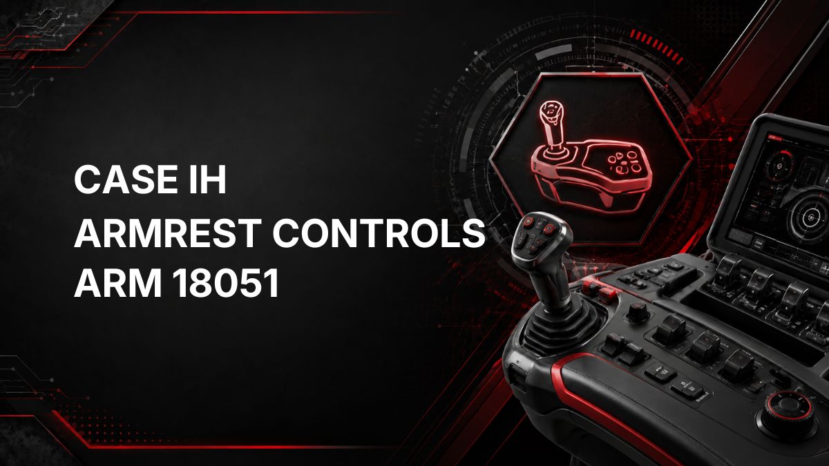
Case IH Tractor ARM 18051 Fault Code: Joystick 1 Y-Axis Voltage Too Low
What ARM 18051 Means
On a Case IH tractor, fault code ARM 18051 is related to the ARM controller, which is associated with armrest controls.
The official description is: Joystick 1 Y-axis position – voltage too low.
In practical terms, the controller is seeing a lower-than-expected voltage signal from the Y-axis position circuit of Joystick 1. The Y-axis is typically the forward/back movement direction of a joystick, but the exact function depends on how the tractor and controls are configured.
This code does not by itself prove that the joystick has failed. It indicates that the ARM controller has detected a low-voltage condition on that joystick position signal circuit.
Likely Symptoms
Symptoms may vary depending on tractor configuration and how Joystick 1 is assigned. Possible symptoms include:
- Joystick-controlled functions may respond incorrectly or not respond.
- A function controlled by the Y-axis movement may be disabled or limited.
- The armrest control system may show a warning or active fault.
- The fault may appear intermittently if the issue is related to wiring, connectors, or movement of the armrest/joystick.
- Normal operation may return temporarily after cycling the key, but the code may come back if the low-voltage condition remains.
Possible Causes
Because ARM 18051 specifically points to low voltage on the Joystick 1 Y-axis position signal, possible causes can include:
- A poor electrical connection in the joystick circuit.
- Damaged, loose, corroded, or contaminated connector terminals.
- Wiring damage causing a short to ground or excessive voltage drop.
- An internal fault in the joystick position sensor or joystick assembly.
- A power supply or ground issue affecting the joystick circuit.
- A fault within the ARM controller, although this should not be assumed until wiring and input checks are completed.
Diagnostic Checks
1. Confirm the Fault
Record the full fault code, controller, and any other active or stored codes. If other armrest, joystick, power supply, or ground-related codes are present, they may help identify whether this is an isolated joystick issue or part of a broader electrical problem.
2. Check Operating Conditions
Note when the fault appears. Useful details include whether it occurs at key-on, only when moving the joystick, when the armrest is moved, or during vibration. Intermittent faults often point toward wiring or connector issues.
3. Inspect the Joystick and Armrest Area
Visually inspect the joystick and surrounding armrest controls for signs of physical damage, spilled liquid, dirt ingress, loose mounting, or abnormal movement. Do not disassemble components beyond your skill level or service information.
4. Inspect Connectors and Harnesses
With the tractor safely parked and powered down, inspect accessible connectors and wiring related to the armrest and joystick circuit. Look for:
- Loose or partially seated connectors.
- Bent, backed-out, corroded, or damaged pins.
- Rubbed, pinched, stretched, or broken wiring.
- Evidence of moisture or contamination.
Do not probe connectors in a way that can spread terminals or damage the harness. Use correct electrical test methods and service information.
5. Check for Electrical Supply or Ground Issues
A low signal voltage can be caused by the signal wire itself, but it can also be influenced by poor reference voltage or ground integrity. Proper testing may require wiring diagrams and approved diagnostic procedures for the specific tractor.
6. Use Dealer Diagnostic Equipment if Needed
Dealer diagnostic software or a qualified technician may be required to view live joystick position data, confirm the Y-axis signal behavior, run controller tests, calibrate controls if applicable, and distinguish between a joystick, harness, or controller issue.
Repair Guidance
Repair should be based on confirmed test results, not the fault code alone. Common corrective actions may include:
- Cleaning and properly reconnecting affected electrical connectors if contamination or poor contact is found.
- Repairing damaged wiring using approved methods.
- Correcting poor power supply or ground connections if identified during testing.
- Replacing the joystick or related control component only if diagnostics confirm it is faulty.
- Updating, configuring, or calibrating the system if required by official Case IH service procedures.
If the fault remains active after basic visual checks, or if joystick-controlled functions affect machine safety, stop using the affected function and have the tractor inspected by a qualified technician.
When to Call a Case IH Dealer or Qualified Technician
Professional help is recommended when:
- The fault is active and joystick functions are disabled or unpredictable.
- No obvious connector or wiring issue is found.
- Multiple ARM or armrest control faults are present.
- Live data, calibration, or controller-level testing is needed.
- Harness testing requires wiring diagrams, breakout tools, or specialized diagnostic equipment.
A dealer or qualified technician can use the correct diagnostic tools to verify whether ARM 18051 is caused by the joystick, wiring, power/ground supply, or the ARM controller.
Find Local Case IH Diagnostic Support
Summary
Case IH ARM 18051 means the ARM controller has detected that Joystick 1 Y-axis position voltage is too low. The issue may be caused by the joystick, wiring, connectors, supply/ground problems, or less commonly the controller. Start with safe visual checks and connector inspection, but use proper service information and diagnostic equipment before replacing parts.