Case IH Tractor ARM 129 Fault Code: Aux 5th Remote Valve Flow Potentiometer
What Case IH ARM 129 Means
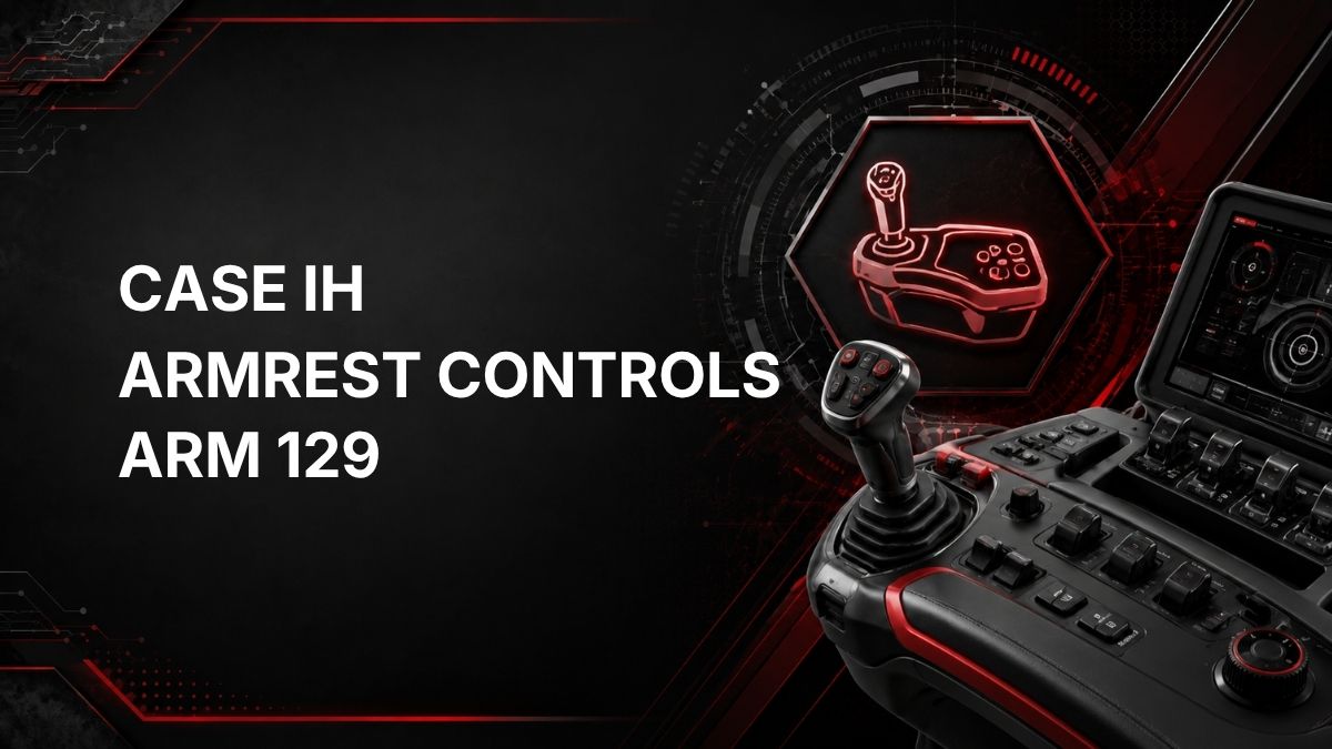
ARM 129 is a Case IH tractor fault code from the ARM controller, which relates to armrest controls.
The official description is: Aux 5th remote valve FLOW potentiometer is failed.
In practical terms, this code indicates that the armrest control system has detected a failure related to the flow potentiometer for the auxiliary 5th remote valve. The flow potentiometer is part of the control input used to set or communicate hydraulic flow demand for that remote circuit. The code does not, by itself, confirm whether the fault is inside the potentiometer, the wiring, the connector, or the controller input.
Likely Symptoms
Symptoms can vary by tractor configuration and software response. Possible operator-noticed symptoms may include:
- ARM 129 fault message or warning displayed on the tractor monitor.
- Limited, erratic, or unavailable adjustment of flow for the 5th auxiliary remote valve.
- Hydraulic remote performance that does not match the selected flow setting.
- Armrest control functions related to that remote behaving inconsistently.
- The tractor entering a protective or limited-function mode for the affected control.
These symptoms are not guaranteed. The displayed code is the main evidence that the ARM controller has detected a problem with the Aux 5th remote valve flow potentiometer circuit or signal.
Possible Causes
Because the official fault description identifies the Aux 5th remote valve FLOW potentiometer as failed, the most likely causes are in that control circuit. Possible causes include:
- Failed or internally worn flow potentiometer for the 5th remote valve control.
- Loose, damaged, corroded, or contaminated electrical connector in the related circuit.
- Damaged wiring, such as an open circuit, short circuit, poor ground, or poor reference supply.
- Intermittent signal caused by vibration, moisture, or harness movement.
- Less commonly, an issue with the ARM controller input or software interpretation of the signal.
Do not replace parts based only on the code. The fault should be confirmed with proper inspection and diagnostic testing.
Diagnostic Checks
1. Confirm the Fault Code
Verify that the active or stored code is ARM 129. If other ARM, hydraulic, or controller communication codes are also present, address them in a logical order because they may affect the same system.
2. Check Basic Operating Conditions
Note when the code appears. For example, record whether it appears at key-on, when adjusting the 5th remote flow setting, during implement operation, or intermittently while driving. This information can help narrow down whether the problem is constant or movement-related.
3. Inspect Visible Wiring and Connectors
Inspect accessible connectors and harness sections related to the armrest control and 5th remote valve flow control circuit. Look for:
- Loose or partially seated connectors.
- Corrosion, moisture, dirt, or damaged terminals.
- Pinched, rubbed, broken, or stretched wiring.
- Evidence of previous repairs or harness strain.
Only inspect areas that are safely accessible. Do not disassemble sealed components or controller connectors unless you have the correct service information and tools.
4. Check for Intermittent Behavior
If the fault comes and goes, gently moving accessible harness sections while monitoring the warning display may help identify a connection or wiring issue. Avoid pulling on wires or forcing connectors.
5. Use Proper Electrical Diagnostics
A qualified technician may use the correct service manual and electrical test equipment to verify the potentiometer signal, reference voltage, ground, and circuit continuity. Required specifications and test points are model-specific and should come from official Case IH service information.
Repair Guidance
Repair should be based on confirmed diagnostic results. Depending on what testing finds, corrective action may include:
- Cleaning and reseating an affected connector if contamination or poor contact is found.
- Repairing damaged wiring or terminals using approved methods.
- Replacing the failed Aux 5th remote valve flow potentiometer or related control component if testing confirms failure.
- Further controller-level diagnosis if the potentiometer and wiring test correctly but the code remains.
After any repair, clear the fault code using the appropriate procedure and operate the control to confirm that ARM 129 does not return.
When Dealer Diagnostics May Be Required
Dealer diagnostic equipment or a qualified Case IH technician may be required when:
- The code remains active after basic connector and wiring checks.
- Multiple controller or hydraulic-related fault codes are present.
- Electrical testing requires model-specific pinouts, calibration data, or service procedures.
- The system needs calibration, software checks, or controller-level diagnostics.
- You are not comfortable testing armrest control circuits or hydraulic control electronics.
Because ARM 129 relates to an electronic control input for a hydraulic remote function, guessing at parts can become expensive. Confirm the failed part or circuit before replacing components.
Locate Your Nearest Case IH Dealer
Key Takeaway
Case IH ARM 129 means the ARM controller has detected a failure associated with the Aux 5th remote valve FLOW potentiometer. Start with safe, basic checks for fault confirmation, connector condition, and visible wiring damage. If the problem is not obvious, use official service information and qualified diagnostics to determine whether the potentiometer, wiring, connector, or controller input is at fault.